Scott Bezek Designs A Fresh Take On Classic Display Boards
If you’ve ever been to the Amtrak 30th Street Station in Philadelphia, you’ve heard a sound that is found in very few places anymore: The clickety-clack of the split-flap boards as they display the latest arrivals and departures. While these relics are mostly memories of a bygone era, artists, makers and engineers are bringing these nostalgic display pieces back to life.
As the adage goes, “Everything old is new again,” and these unique display boards are popping up all around trendy restaurants and expensive homes. The problem? The price tag. One high-tech version that debuted at CES 2018 merges the classic clattering flaps of a retro train board with modern internet technology—and costs upwards of $3,500. That’s a lotta scratch to hear the fluttering of shuffling letters.
Scott Bezek has always loved these electro-mechanical displays, be he wasn’t about to empty his bank account to get one. He knew there had to be a better way, and so he set out to learn how to make a split-flap board himself.
Reimagining A Classic Display Board
For the next two-and-a-half years, Scott spent much of his spare time researching, designing and prototyping his version of a split-flap display board. “Ultimately, I wanted to design a split-flap display that can be built in small or single quantities, customized and put together for not too much money,” he says. “This meant using widely available materials and avoiding any tooling with a high up-front cost.”
To keep it accessible, everything Scott built is open source. The 3D model is designed in OpenSCAD, the driver electronics board is designed in KiCad and the driver firmware is written using Arduino.
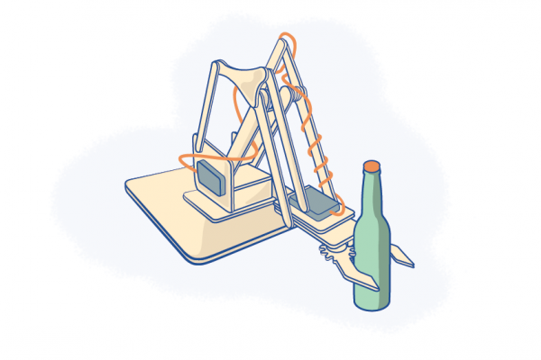
“Since this was my first time designing something for laser cutting, I started by creating a simple box in OpenSCAD, which differs from other CAD tools in that it uses a programming language to define solid shapes and combine/subtract/extrude them into complex designs,” he explains. “As a software engineer by day, creating 3D models by writing code was really appealing!”
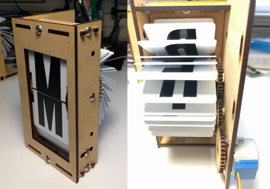
Each module’s frame is basically a box that uses captive-nut joints (t-slot joints), which hold a nut in place and allow a bolt to hold the perpendicular pieces together. But the most challenging part of the 3D design was the spool.
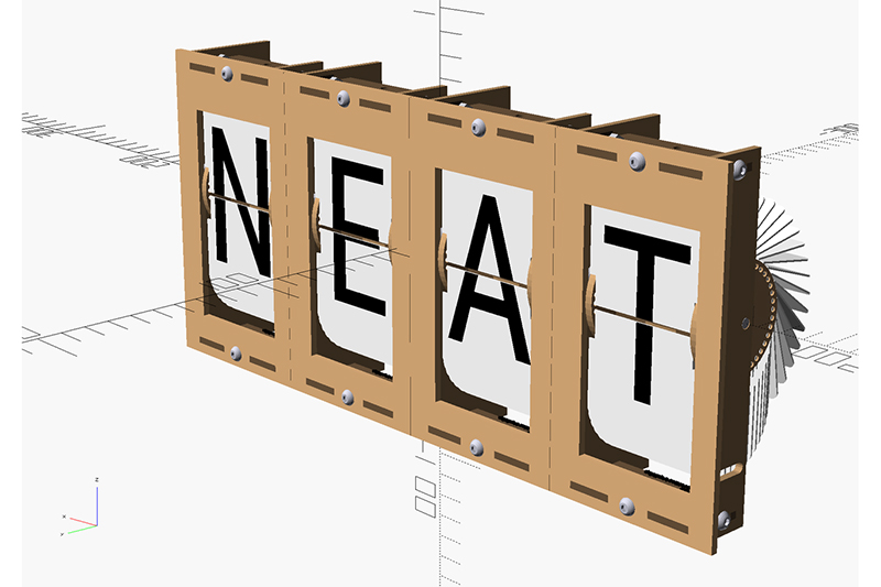
“The spool is made from eight separate laser-cut pieces and can hold 40 letter/number flaps (so there are 40 holes around the circumference),” Scott says. “The four center struts provide rigidity and prevent the spool from twisting when it’s driven by the gear on one end.”
Here’s what the digital models look like:
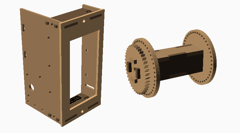
Creating these 3D designs in code allowed Scott to easily adjust elements of the design by simply changing the parameters. This kind of parametric design/modeling may take a bit longer to initially set up, but it is great for iterating prototypes because it’s faster for making changes—saving much time (and aggravation!) in the long run.
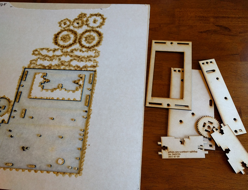
Once the design was finalized, Scott chose MDF for the laser cut parts because this material is affordable, consistent in thickness and softer (than acrylic, for example), making it ideal for pieces that need to slot together. Having some give allows for a nice, tight fit without breaking any tabs when the pieces are slotted together.
To keep costs low, Scott used store-bought three-inch vinyl stickers to hand-letter the flaps. “It’s a slow, painstaking process to cut each letter in half and carefully align and apply them to the flaps,” Scott says. “Even after some practice creating my first module, it still took 90 minutes straight to cut and apply the stickers for my second module.”
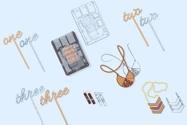
Once the split-flap display module was built, it was time to get it moving. Using KiCad, a free open-source tool, Scott was able to design the circuit/schematic and eventually build a custom PCB.
But one of the most challenging aspects was writing the Arduino code. “The first trick is getting the motors to spin quickly; you can’t just sequence them at full speed from stopped because their inertia will cause them to miss steps and just vibrate in place rather than turning,” he says. “So the controller needs to accelerate and decelerate to start/stop smoothly.”
The next problem was with the motors themselves. The inexpensive 28BYJ-48 motors Scott used had two variants (not labeled), with one of the variants missing an integer number of steps per revolution. So he had to write the control code in a way to track revolutions and keep the spool aligned.
The final challenge was getting the sensor auto-calibration to work. “Since the Arduino controls the angular rotation precisely, it can predict a small range where it expects the IR sensor to detect the home position,” Scott explains. “If the IR sensor detects the home position earlier or later than predicted, it assumes something went wrong and the module switches into calibration mode. In calibration mode, it rotates slowly to find the home position again and resets its frame of reference.”
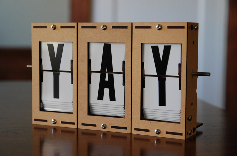
Once he worked through all of the engineering issues, he was able to perfect the design. Check it out:
Growing The Split-Flap Side-Hustle
Scott made his split-flap display open-source so anyone could build one. But he also saw an opportunity because not everyone will take the time to make all the components, but they will buy a kit.
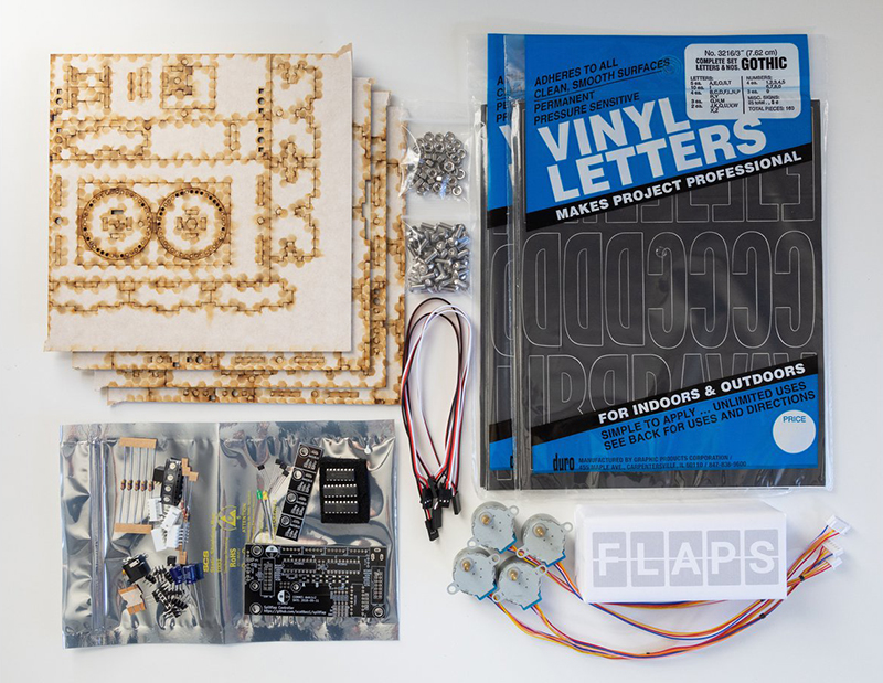
While the Split-Flap Display Kit doesn’t come complete with an Arduino or power source, the kit does contain everything else needed to make a split-flap display—from the laser-cut parts to the motors, sensors, calibration magnets, and nuts and bolts.
To complete the buyer’s experience and build the Split-Flap brand, Scott customized the kit’s packaging by using a stencil and a little spray paint. Smart packaging doesn’t have to be expensive!
Picked up a laser-cut stencil from @Ponoko yesterday so I could spruce up splitflap kit boxes with a little spray paint! pic.twitter.com/4UfElT5MMd
— scottbez1 (@scottbez1) November 7, 2018
He even designed a font to mimic the split-flap look to further brand recognition.
My favorite part is that the “split” line in splitflap lettering makes for a great stencil font that’s on-brand! pic.twitter.com/xsXOeq1nQt
— scottbez1 (@scottbez1) November 7, 2018
Scott intentionally limited the number of kits he would offer for sale. He wanted to not only ascertain if there was buyer interest but also learn just how much time it would take to pull everything together. Assembling kits may seem easy, but there’s a fair amount of work to it when scaling production, so that’s a consideration for any seller when determining how to go to market.
So if you can’t get your hands on a kit, you can still make your own split-flap display by following Scott’s tutorials on GitHub and Imgur. You can also connect with him on Twitter and YouTube.
And if you’re ever in Philly, make sure to stop by the Amtrak station to see its original split-flap board. But don’t wait; Amtrak announced in November 2018 that it is replacing its boards, which were installed in the 1970s, with a new $11 million digital system. However, Philly residents and lawmakers objected so vehemently that the rail agency seems to have relented—for now. In December 2018, Amtrak and Pennsylvania representative were in talks about how to keep its hardy black-and-white information board.
As Inga Saffron wrote in a Philly.com op-ed: “Even though you probably carry a screen in your pocket, chances are the first thing you do when you enter 30th Street Station is belly up to the information desk and scan the board. You wait for the satisfying clickety-clack of the flaps, which echo the clickety-clack of the trains as they race along the tracks. The mechanical board is the physical manifestation of motion. You are traveling even before you’ve left the station.”
While digital may be efficient, it can’t evoke this kind of emotion, nostalgia and appreciation. So whether it’s an enormous sign in a train station or a small version you can build yourself, split-flap display boards can help you step back in time—even if it’s just for a minute.