 In 2008 I sought to try and quantify the kerf of our laser cutter, or how much material the laser cutter burns away when cutting specific materials.
The idea behind providing this information is so you can make a more educated guess of what sizes to draw your shapes if you are needing a tolerance fit. This information is particularly relevant if you are creating inlays and slotting joints*.
Please note these are 2008 figures, and have changed over time. Prototyping for yourself is the best way to guarantee the perfect result but hopefully this info will give you an idea of what to expect.
So anyway here are the results…
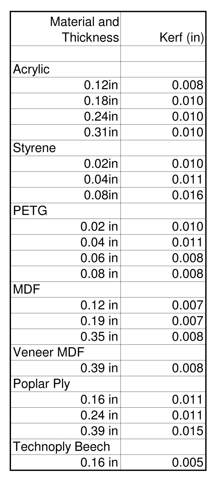
For those using imperial:
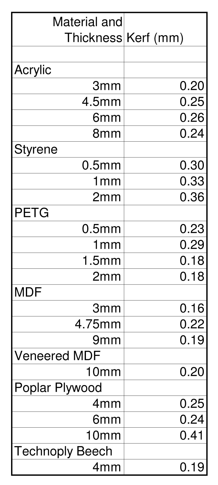
And for those on the metric system:
So what does that mean?
If you are wanting to combine/inlay materials, say a white square within a red one, or something like ColinFrancis jewelry, then you can use this data to help determine what dimensions to create the shapes in your eps files at.
If you were to draw some parts to be cut from 3mm acrylic as dimensioned below,
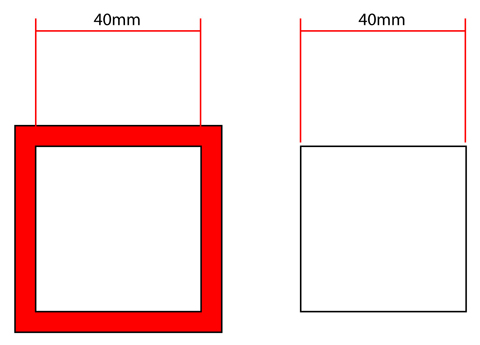
the white square on the right would end up at 39.80mm and the hole in the middle of the red square would be 40.20mm.
However if they are dimensioned to allow for the laser burning material away, both the hole and the white square will come out at 40mm and they should fit snugly together.
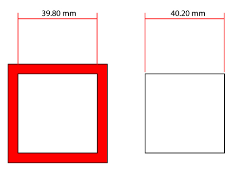
This video shows what I am talking about. The square labeled ’40’ shows what happens in the first diagram, or when the dimensions for the hole and the bit to go into the hole are the same. The square labeled ‘40.20’ shows a square drawn to allow for the laser kerf. The parts fit snugly together with a nice click.
Anyway, I hope that can be some inspiration for you. Happy making.
* slotting joints also rely on the thickness of the material being consistent to be successful. All our materials have a thickness tolerance of +/- 10% of the material thickness. I will create a post in the future which will address slotting joints in more detail but for now you can refer to here for notes about nodes or ask a question in the forums.

12 Comments
Excellent information! I have been wondering about how to tackle Ponoko laser kerfs within my SketchUp plugin – now I have all of the information I need (I just have to find time for coding).
Could you cut and paste those numbers into the post instead of using screenshots of Excel?
This is super helpful!!!! Thanks so much for the research!
Bre
For thin materials it wouldn’t make much difference, but for some jobs one should consider the angle produced by the laser’s cone-shaped beam.
I.e. the vertical edge has a slight taper on it, (depending on the focus point and the lens used) so the 40mm square could be a wee bit bigger on the bottom than the top.
It follows that for a *really* neat fit, one of the pieces should be inverted.
The thicker the material, the more taper from top to bottom of the cut.
Bob
Exactly what I needed,
many thanks for this detailed information.
Gilbert
This is somewhat of an oversimplification that can get you into trouble. The laser kerf width is very much a function of the speed of the laser. Long straight edges have a narrower kerf than slow curved edges.
The kerf is also dependent on the cutting speed, which is affected by the radius of curvature of the cutting path… therefore, this experiment should be repeated using circles of different diameters.
Also when expanding a shape to compensate for kerf, you are supposed to replace corners with a curved path–otherwise, the corners cut in too far and become curves.
Great post. Thanks!
Also I see a bug: The whole page is duplicated below this comment window.
It shouldn’t be too hard, and in saying that I’m sure it’s been done already, to process a vector file and add lines showing estimated widths.
The above post is excellent. It further proves my theory that you can never do anything right on the internet.
Instead of forcing folks to do, at their expense and Ponoko’s benefit, 3 prototypes to get their design spot on, they now only need 1 or 2, saving them money Ponoko would otherwise be getting, and what thanks do you get? Quibbles about the last 0.1mm, arguments that you should repeat the experiment for them, for free, for every possible variation of cut, and so on.
You should give them free materials. You should be doing the design for them, and troubleshooting it. You should be paying them for your laser time. Oh wait! That’s not how life outside the internet works!!
It would be useful to know the weight of your different sheets of material.
In kilos. For simplifying the math when calculating the area (and relative weight) of the patterns.
Does anyone know if Inkscape can calculate the area of an object?
How about other vector apps?
Thanks!
I might be thinking wrong, but, in the above example, how is 40 mm into 40 mm a better fit than 39.80 mm into 40.20 mm? They both add up exactly. It would be a problem if it was 39.80 and 39.80 (too loose/would fall through), or 40.20 and 40.20 (too tight/would not fit inside). No?
Comments are closed.